The Facts on LED Lighting.
How does LED work?
What are LED’s?
LED stands for Light Emitting Diode. An LED is a semiconductor (diode) emitting light when current flows through it. Semiconductor materials used by LEDs, convert electrical energy into visible electromagnetic radiation, in other words, into light. Visible Light
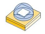
The stimulus is therefore created by electric current through the diode (more specifically through the junction). The diode through which the electric current flows is uni-directional, as are all diodes: light will only be created if direct current flows through it in the ‘right’ direction, i.e., from the anode (positive pole) to the cathode (negative pole).
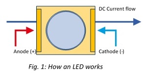
Impact of current on luminous flux.
The amount of light generated, is nearly proportional to the amount of current flowing through the diode. For lighting purposes current-controlled supplies (‘constant current’) are always used (see Section C.3).
LED “Semiconductor” structure.
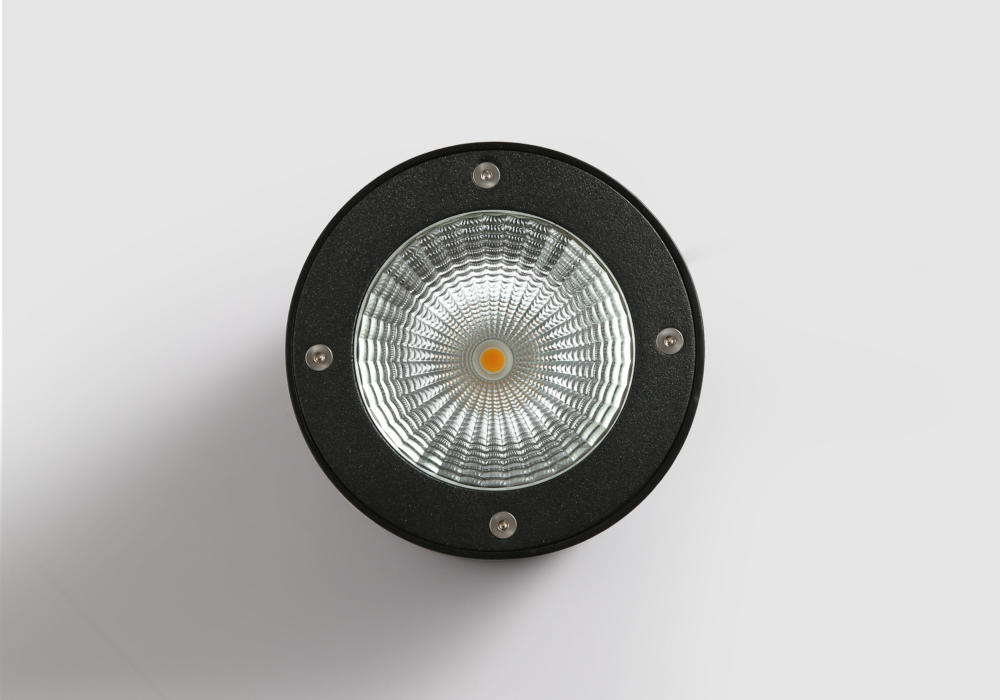
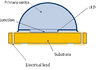
The combination of LED (semiconductor), housing and primary optics is referred to as an LED component. This LED component covers and protects the LED, ensures that the heat generated internally is also dissipated and includes a primary optics system, i.e., a small lens, to collect and emit the light generated by the LED in a defined pattern.
LED colour of light.
The LED emits monochromatic light. The colour of the light depends on the materials used during production, which can be all saturated colours from the visible spectrum, from violet and blue through green to red.
White light can be produced as follows:
1 . Bichromatically :
The most prevalent way is to provide a blue LED with luminescent (light-emitting) material, which converts part of the blue light into white (or rather ‘yellow’) light. The composition of said luminescent material determines the resulting light’s colour temperature (to read more about colour temperature, see below in this section).
2. Trichromatically:
By blending red, green and blue (RGB). This technology is not applied very often in functional lighting.
Through combinations of white LEDs in accordance with the first principle with red or amber-coloured LEDs. In this case various colour temperatures are possible with a single module.
2. Types of LEDs
LED components[1] can be classed in accordance with various criteria, such as colour, power, construction design. These classifications are not standardised and are subject to change or shift depending on technological developments. In addition, categories overlap: for example, high-power (HP) and low-power (LP) LEDs differ in terms of power, but also construction design.
[1] LED components not only involve – contrary to LED chips – the active material, but are also fitted with an electronic connections and potentially primary optics and/or phosphor layer.
Colour:
Phosphor-converted LEDs typically produce blue light, which is converted into white light by means of a phosphor layer. Other, pure LEDs do not feature a phosphor layer, but emit pure colours (e.g., red, green, amber or blue) or IR or UV waves. The colour depends on the material used.
Power:
- low power (≤1 W )
- high power (1-10W)
[1] LED components not only involve – contrary to LED chips – the active material, but are also fitted with an electronic connections and potentially primary optics and/or phosphor layer.
Construction design:
- lead-frame devices
- LED chips on substrates
- chip-scale package
- chip-on-board
Low power LED structure
Lead-frame constructions are primarily applied to low-power LED’s. The LED chip is placed on the lead-frame, and is subsequently surrounded by a plastic housing. In phosphor-converted LED’s, the central cavity is filled with a silicone layer containing phosphor. Both lead-frame and housing act as reflectors in this design for a portion of the radiating light. That is also the reason why the optical properties – including reflection power and degradation of material – contribute to light maintenance in the long term: the better the material retains its reflecting properties, the lower the degradation. The choice of plastic is also considered on the basis of optical properties, as well as cost price and ability to process. The most prevalent materials for housing include thermoplastic materials such as PPA and PCT, and thermo-setting resins such as EMC and in some cases even silicones. Currently specific types of low-power LED’s such as multi-die LEDs (with 2 chips) deliver a higher luminous flux. In blue or UV LEDs, due to the higher density blue lights, however, increased degradation of the material occurs, which has a negative impact on service life and colour rendering.
TOP BOTTOM
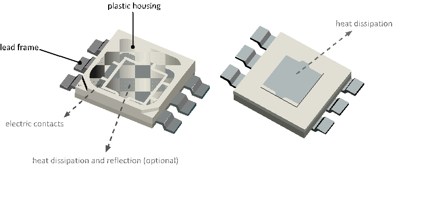
The above Figure: LED lead frame with plastic housing (in low-power LED)
High Power LED Structure
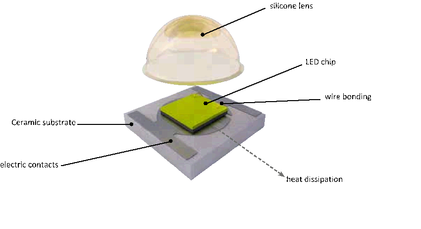
Ceramic substrates are typically applied in high-power LEDs. A phosphor coat and primary optics, generally from silicones are placed on the substrate. This construction has the following properties:
- Good heat dissipation to the PCB (lower internal thermal resistance)
- Direct emitted light and little reflection
- Good colour stability across the entire cut-off angle
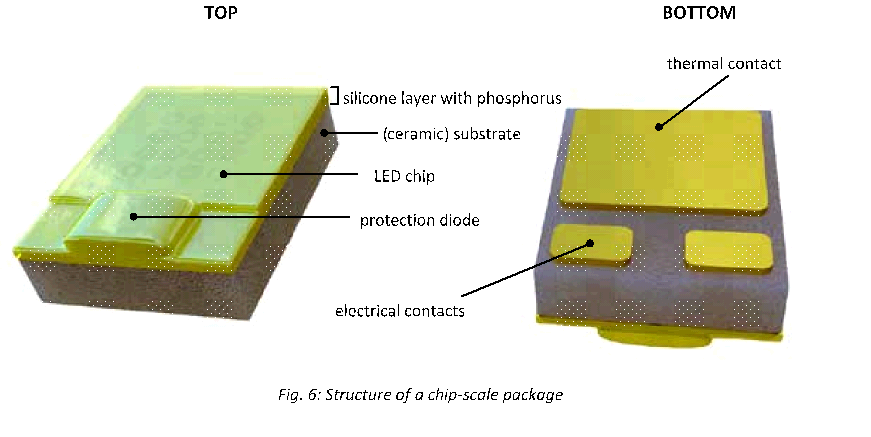
The Chip-scale package.
The chip-scale package is a miniaturisation of the (low- or high-) power LED. This LED package features minimal housing and is remarkably compact (1 to 4 mm2). For low power, even smaller versions have been developed (0.5 mm2). The heat is channeled directly from the chip to the PCB through electrical contacts. As the distance to be covered is kept this short, heat dissipation is highly efficient.
Chip-on-board technology:
In chip-on-board technology – typically applied in phosphor-converted LEDs – several chips are fitted on a single substrate and mutually connected. A silicone coat is applied with phosphor. The substrate generally consists of a ceramic material or highly reflective (polished) aluminium.
OPEN CLOSED
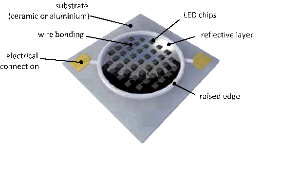
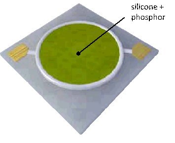
Fig. 7: Chip-on-board technology construction
Stuctural Design can impact operating life in LED’s
The development of the optical properties in function of time under the influence of light and heat has a major impact on the maintenance factor of LEDs. Stability is optimal for high-power components (e.g., high-power and COB), and lower for plastic low-power LEDs. Low-power LEDs also result in higher yield with a sophisticated design.
3. INTEGRATION LEVELS
LED Design variations
LED light sources can be applied in many ways. According to international standard IEC 62504/CIE TC 2-66 (‘Terminology of LEDs and LED assemblies’), the following levels of integration can be distinguished:
LED package or LED component.
This is a single component consisting of one or more LED chips, with or without optics and thermal, mechanical or electrical interfaces.
LED module.
A LED module consists of several LED components, mounted on a PCB (printed circuit board), with or without integrated electronics.
LED lamp.
This is an LED module fitted with a lamp cap. There are multiple options in this design filling the retrofit LED lamp market.
LED light engine.
LED module or lamp with driver, suitable for direct connection to the mains voltage.
Organic Light-Emitting Diode or OLEDs
OLED stands for Organic Light-Emitting Diode. As the name suggests, it involves a variant of the traditional LED. However, whilst LEDs are based on crystalline, inorganic material (e.g., gallium nitride), OLEDs use organic macro-molecules based on hydrocarbon compounds to produce light.
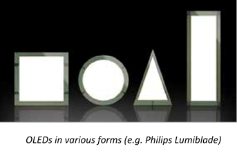
The difference between OLEDs and LEDs
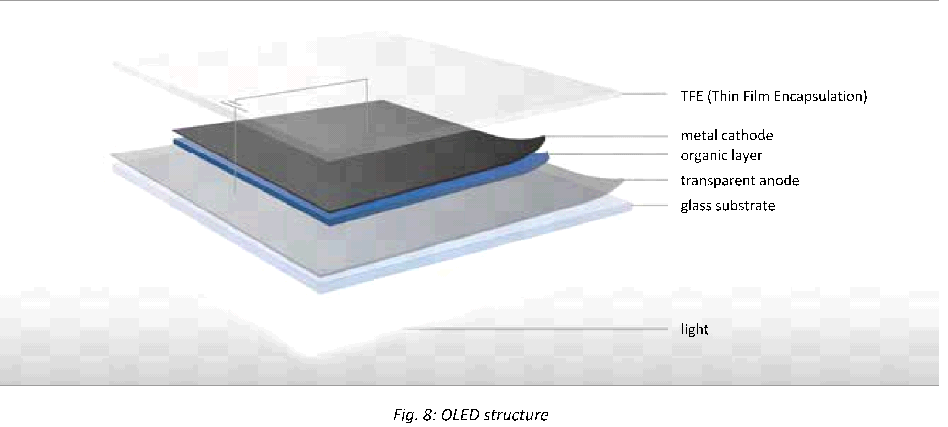
The difference between OLEDs and LEDs not only lies in the material, but also in the mode of operation. Whilst an LED is a typical light point source, OLEDs are used to spread light over a specific surface. In practical terms, the organic light-emitting particles applied in a wafer-thin layer onto a substrate made from glass or another transparent material and connected to a cathode and anode. The layer lights up whenever voltage is applied to the cathode and anode. By combining the correct materials, OLEDs are able to generate light in a specific colour.
Today OLED technology is still being developed. In terms of performance and service life so far they are certainly not in the same league as LEDs. OLEDs achieve light efficiency of 60 lm/W compared to 220 lm/W for LEDs.
|
OLED |
Road map | ||
| year | 2015 | 2016 | 2018 |
| Luminous efficacy | 50 lm/W | 90 lm/W | 120 lm/W |
| Life time (L70 @ 3 000 cd/m2) | 20,000 h | 40,000 h | 60 ,000 h |
| Brightness | 3,000 cd/m2 | 4,000 cd/m2 | 5,000 cd/m2 |
| Lumen output | 10,000 lm/m2 | 15,000 lm/m2 | 20,000 lm/m2 |
| Colour Rendering Index (CRI) | >90 | >92 | >95 |
| Max. dimensions | 150*150 mm | 320*320 mm | 400*400 mm |
The presence of organic materials – which age relatively fast and are quite sensitive to air and moisture – results in a fairly limited lifespan. Today 20,000 burning hours are assumed (with 30% decrease in light output, and a continuous control of 3,000 cd/m2). However, this result was obtained with non-standardized measurement and extrapolation methods.
Lighting with LEDs
LIFESPAN
USEFUL SERVICE LIFE
In general LEDs have a long useful service life. At the same time, service life is a complex detail, which always goes with a concrete situation or installation, and the related maintenance factor (see below). If you opt for an LED lighting installation, always take into account the expected lifespan: do you want the installation to last 10, 15, 20… years? This information is important to make the correct calculation (see also D.2. Choice criteria).
DEPRECIATION
Every light source whether it be fluorescent lights or LEDs, is subject to depreciation. This means that the light output from the light source gradually decreases over time. In traditional light sources, this depreciation is taken into account by everyone in the same way as standardised lamps are used with a fixed depreciation and a limited number of burning hours (16,000 hours).
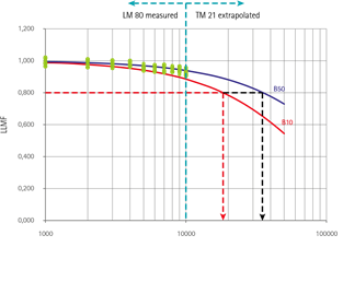
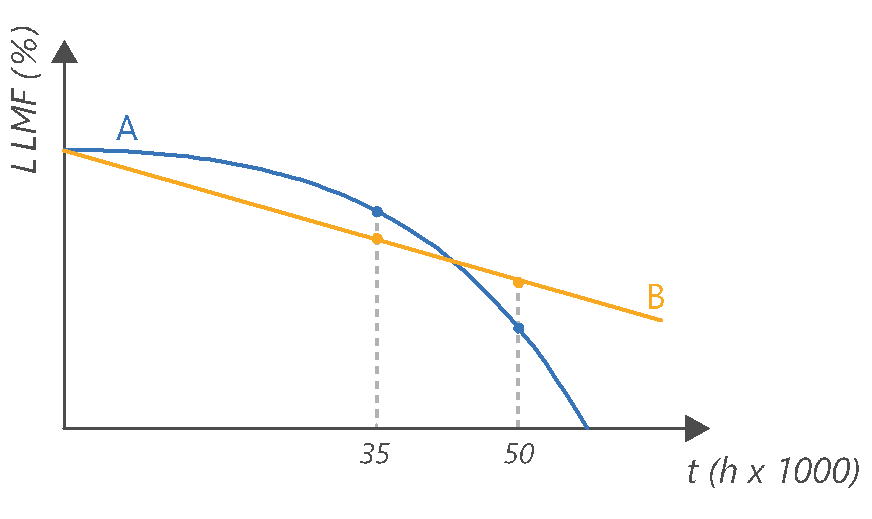
It is different for LEDs: there are so many different types of LEDs that depreciation varies hugely. In addition, degradation is highly impacted by the quality of the LEDs, but also by the LEDs’ internal temperature, which in turn depends on external factors such as control, ambient temperature and quality of heat dissipation around the LEDs. The degree to which the luminous blocks deteriorates from the light source, is shown in the LLMF (Lamp Lumen Maintenance Factor), which indicates how much light a light source still gives off after a specific number of burning hours. See “How much light is left after five years” for information on LED degredation.
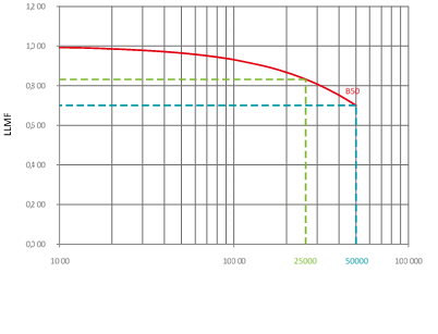
In the graphic below we see light degradation for a luminaire LLMF 97% after 50,000 hours. (green) compared to a luminaire with a LLMF of 70% after 50,000 hours. In fluorescent lights it involves a steady depreciation, whereby the light level is brought back to 100% each time by lamp replacement (blue curve). In LED luminaires the depreciation curve varies greatly. Hence LED lighting life an the ability for maintenance is of a greater concern with the dominance of LED lighting on the market.
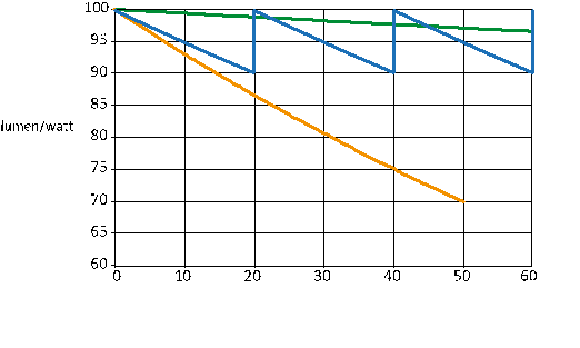
burning hours (h x 1000)
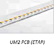
— U7 luminaire with met L97 @50.000 h (ETAP)
— LED luminaire with L70 @50.000 h
— T5 fluorescent lamp
Fig. 10: LLMF of LED luminaires compared to fluorescent lighting.
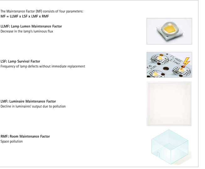
MAINTENANCE FACTOR
In practice the deterioration of the light source (LLMF) is not only important, but we have to take into account the deterioration of the complete installation: the lamps’ light output drops, lamps break and luminaires are soiled by dust and other dirt. The space itself also gets dirty – a recently painted wall for example, will better reflect light than a dirty wall. That is why, in the calculation of an installation, a maintenance factor is applied that takes into account the decrease in the luminous flux (see box text). In this way you can rest assured that the installation will continue to satisfy the suggested lighting level after 5 or 10 years.
Maintenance factor in fluorescent lighting
Clear rules and international standards are in place for traditional light sources such as fluorescent lamps to calculate an installation’s maintenance factor. Typically four aspects are taken into account: decrease in luminous flux produced by the lamp, frequency of lamp defects, soiling of luminaire and soiling of the space itself. For fluorescent lighting there is a general consensus about the calculation of the maintenance factor. Depreciation and service life of the lamps have been proven in practice and there is little difference or no difference at all between manufacturers. In addition, the luminaire’s design has no impact on the lamp’s depreciation and it is assumed that the lamps are replaced regularly, so that there is generally little discussion about the maintenance factor of fluorescent luminaires.
Maintenance factor in LED lighting
This is not the case for LEDs, however, where the maintenance factor depends on many more factors. It starts with the choice of LEDs. Today there still is a major quality difference between manufacturers and the type of LED (low- or high-power) and phosphor composition (colour temperature and colour rendering) are also decisive in terms of maintenance of luminous flux and lifespan. It furthermore involves a fairly recent technology, which is evolving very rapidly. Due to a lack of necessary knowledge and information today the majority of LED and lighting manufacturers use an LLMF of 80% after 50,000 hours for the sake of convenience, which means that they assume that the LEDs only achieve 80% of their initial light output after 50,000 burning hours, regardless of the quality of the LEDs.
Contrary to fluorescent lighting, the luminaire design also plays a major role. The light output and lifespan of LEDs is highly dependent on their working temperature. The better they are cooled, the lower the depreciation and the longer they will last. Heat dissipation in the luminaire is therefore also critical. However, luminaire design today is seldom taken into account when determining the maintenance factor. In practice each LED luminaire has its own maintenance factor, which makes it impossible to determine a generic value applicable to all fittings.
Impact on your installation
Inaccurate calculations can in practice have major consequences. If the maintenance factor is assessed too optimistically, the installation will no longer satisfy the desired lighting level after a few short years. Conversely, too pessimistic a maintenance factor will lead to an oversized lighting installation, with too many luminaires and exaggeratedly high installed power, which drive up purchase price and power consumption.
E.g., impact of the maintenance factor on a lighting study with U7 luminaires in an office space measuring 9 x 14.4 m:
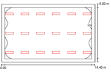
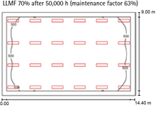
According to the lighting study with correctly calculated maintenance factor, we need 18 U7 luminaires and an installed power of 0.86W/ m²/100 lx (left) for this space. The use of the general maintenance factor (right) would lead to an over dimensioned installation: 24 U7 luminaires and an installed power of 1.25W/m²/100 lx.
Maintenance factor at ETAP
The maintenance factors ETAP uses in its lighting studies are carefully determined in accordance with international standards. In practice, we find that ETAP’s maintenance factors are usually much higher than the value generally applied. That is because we focus on two specific factors. Firstly, we always use high-quality (mainly ceramic) LEDs in our luminaires from manufacturers that publish concrete and verifiable data about the light output and service life of their LEDs. In practice this takes place on the basis of the LM80 and TM21 standards, validated by the Illuminating Engineering Society (IES), an international authority on the subject, which provides us with an objective assessment criterion for the performance of the LEDs.
Secondly, we pay close attention to the heat management of our LED luminaires and take this into account. We have the right infrastructure in our labs to channel the junction temperature between the PCB and the LED. In this way we know the working temperature of the LED and we are able to assess the effective depreciation and life expectancy of the LEDs more accurately. We then include them in the calculation of the maintenance factor in our lighting studies.
ETAP provides a table in which you can find the correct maintenance factor for all ETAP LED luminaires, in accordance with the suggested environment and user period. In this way, we provide our customers with a reliable lighting study, as well as with the certainty that the installation will perform as required.
An example:
In a lighting study with U7 in an office environment, the maintenance factor is calculated as follows: 99% (LLMF or lamp maintenance factor) x 1 (lamp failure in LED luminaires is nearly non-existent, and therefore has no influence) x 0.94 (soiling of room) x 0.95
(maintenance factor for closed luminaire) = 88%. This means that 88% of the luminous flux remains after 25,000 hours. After 50,000 hours
87% of the luminous flux remains
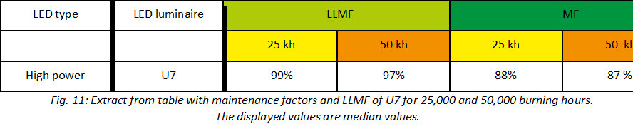
The complete table of maintenance factors is shown in Appendix 1.
LLMF
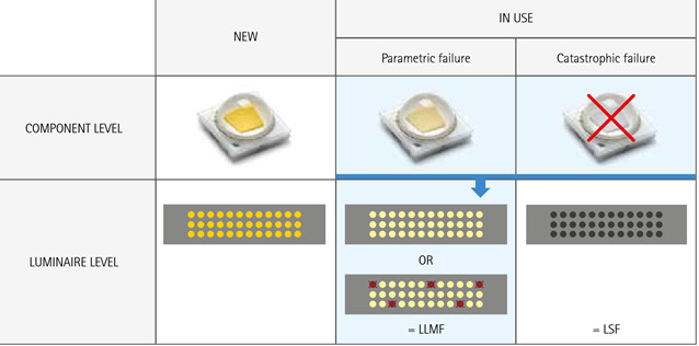
The figure that reflects the drop in luminous flux of the light source (LLMF) takes into account failing LEDs, and deterioration of the light output over time. How do we determine this LLMF? We distinguish between the service life of LEDs at the component level and at the luminaire level.
At the component level we take into account the gradual deterioration of the luminous flux of the LEDs (parametric failure or B-lifetime), and the potential breakdown of LEDs (catastrophic failure or C-lifetime).
At the luminaire level the complete failure of a luminaire is not relevant (see Luminaire Survival Factor). The LLMF corresponds with the B-lifetime at the luminaire level and hence takes on board the parametric as well as catastrophic failure of the individual LEDs in the luminaires.
In order to achieve an accurate, reliable LLMF for our luminaires, we carry out a ‘principal component analysis’:
- We determine the parametric failure at the component level in accordance with objective LM80/TM21.
- We are unable to calculate the catastrophic failure, but prefer to collaborate with manufacturers who make accurate data available.
Whenever no measurement data are offered, we depend on electronic reliability models (MIL-HBK-217F).
Operating Hours Operating hours
Fig. 13: ETAP provides the LLMF after 25,000 and 50,000 burning hours for all its LED luminaires.
Fig. 12: LLMF is determined in accordance to the LM80/TM21-method recommended by IES.
You will find both the LLMF and the maintenance factor for our LED luminaires on our website. We always publish both values for two periods: 25,000 or 50,000 burning hours. In this way you will know how much light your luminaires will give off after a period of use relevant to you.
PERFORMANCE
EFFICIENCY
Cold white LEDs with a colour temperature of 5,000 (kelvin) these days reach more than 240 lm/W in lab conditions. LEDs with a lower colour temperature from 2,700 to 4,000 K (most commonly used for lighting applications in Europe) and Ra80 or higher usually have a lower efficiency. In these colour temperatures, efficiencies of 200 lm/W and more are commercially available today.
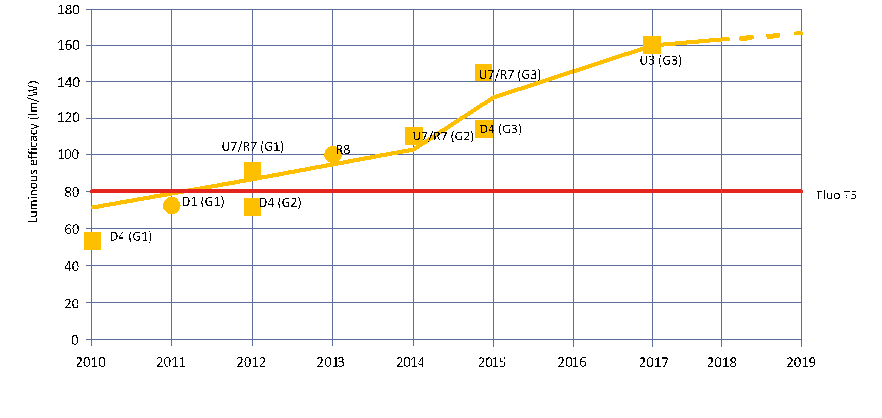
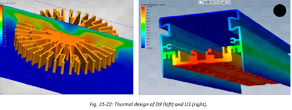
Fig. 15: Evolution of the specific luminous flux of LED luminaires at 3,000 K, with indication of different generations (G1-2-3) of some ETAP products, at junction temperature under normal use (hot lumens)
This curve is based on the actual performance of the LEDs in concrete applications, which differ from the data published by the manufacturer due to product-specific electrical control and thermal behaviour.
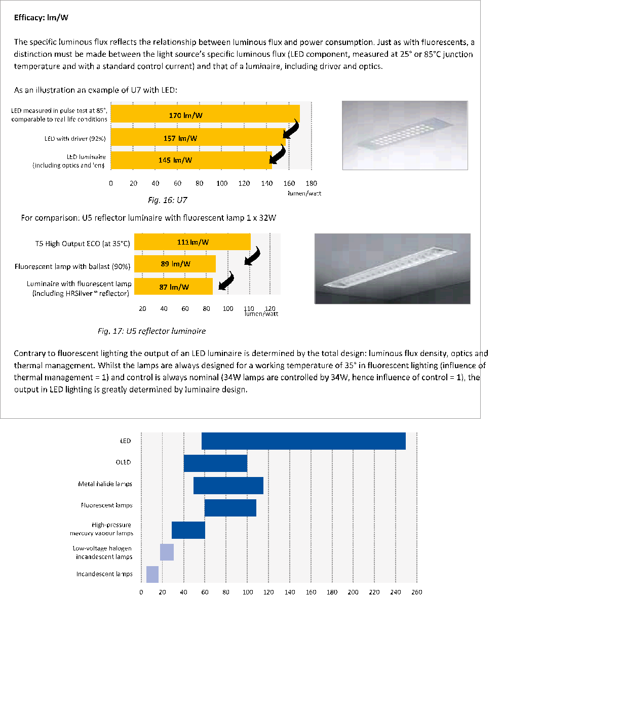
Fig. 18: Typical values for efficiency of light sources
LEDs with high colour temperature and therefore colder light have a higher efficiency level than the same LEDs with lower colour temperatures. The luminescent material used to create warm white, contains more red and the efficiency of this red component is lower than that of yellow, which is why the overall efficiency of the LED drops.
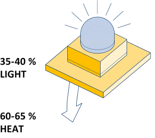
THERMAL MANAGEMENT
What generally applies is the better heat dissipation, the more efficient the LED (lighting). Depending on LED performance 35-40% of energy is converted into visible light and 60-65% into heat within the component (dissipation). By way of comparison: fluorescent lights emit some 25% of converted power as visible light. But the difference resides in the fact that in fluorescent lighting some 40% of energy is also emitted in the form of infrared or heat radiation. The remaining 35% are converted into internal heat and UV.
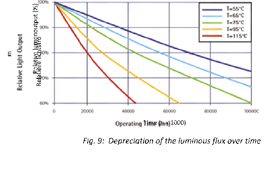
The luminous output of LEDs drops gradually depending on increasing junction temperature. At lower temperatures, the luminous output increases: LEDs always work better as their operating temperature drops.
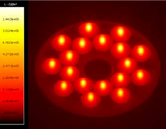
led = 18x Cree XP-G2 R2 4000K @ 350 mA
Temperature not only impacts luminous output. Functional lifetime is also affected whenever a critical temperature is exceeded.
Good temperature management is therefore critical. Heat extraction from the LED to the environment takes place in successive steps (through various heat resistances):
- The heat generated by the LEDs is led through the substrate to the soldering point (1, internal in LED).
- From there the heat is spread across the LED circuit board (2).
- A thermal interface (3) or TIM (Thermal Interface Material) ensures optimal heat transfer between PCB and heatsink (4).
- The heat is carried off to the environment through convection and radiation.
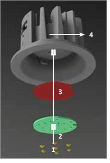
Heat Sink
Free flow of air around the luminaire is essential to proper heat emission, which is why the thermal behaviour of an LED appliance will be different for surface-mounted and recessed luminaires, and for recessed luminaires, sufficient free space around the luminaire must be provided (hence no insulation!). Maintenance of the heatsink (keeping it dust-free) is important as well for good temperature management.
COLOUR ASPECTS
COLOUR RENDERING – TM-30-15
Colour rendering in lighting has been represented for years by the Colour Rendering Index (CRI). This index was developed in the course of the last century. Yet the system has a few major flaws, as a result of which the IES (Illuminating Electrotechnical Society) published a report in 2015 (TM-30-15) in which a new measuring method is presented.
Basic principle CRI
The colour rendering index of a light source reflects how reliable colours are rendered compared to a reference source when an object is illuminated by said light source. In order to determine this index, the reflection of a set of colour samples is compared when it is successively illuminated by a test light source and by a reference illuminant.
For low colour temperatures the reference light source is a black radiator; above 5000 K the comparison is made with the daylight spectrum.

Criticism of the old system
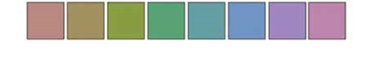
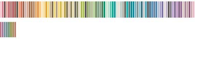
The old index (CRI) is based on a limited and by-now outdated colour spectrum. For example, the traditional Ra value is the average CRI over a set of 8 low saturated pastels:

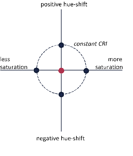
- The CRI provides too little information: a high CRI score indicates that the colour fidelity is good, compared to the reference. At a lower value, however, you do not know in which direction your test light source deviates from your reference (see Fig. 24), and whether it is necessarily bad. In other words, the CRI is no measure for subjective preference/acceptance.
- LED technology offers a lot more options with respect to colour variations than traditional light sources. Today there are numerous LED components, for example, with a particularly wide colour range, which cannot be quantified by the CRI.
- The abrupt transition between the two reference light sources (under or above 5000 K – see above), provided the option of the subjective documentation of light sources.
IES improvement proposal
The new measuring system proposed by the IES consists of two principles: an improved version of the CRI metrics, i.e., the Colour Fidelity Index ( CFI), and an additional parameter, the Colour Gamut.
Colour Fidelity Index (CFI or Rf):
The CFI is based on a much richer colour set than the CRI, i.e., 99 colour samples (Colour Evaluation Samples or CES). Whilst the deviation used to be checked between the test light source and the reference illuminant for 15 colours, it is now done for 99 colour samples. These 99 colour samples represent a synthesis of an extensive database of >100,000 objects) and provide a more uniform coverage of the range (including saturated colours).
The colour model used for the (CIE-CAM08-UCS) calculation furthermore represents a more accurate interpretation of colour distances. This means that the various hues cover approximately the same surface area in the colour space. In practical terms, the deviation compared to the reference light source is calculated by means of this improved colour model, for 99 colours. The average deviation for these 99 colours results in a score between 0 and 100, contrary to the CRI, which can be a negative value as well.
Rf vs CRI for existing light sources
For traditional light sources (e.g., incandescent lamps, metal halide lamps) there is a strong correlation between Rf and CRI.
Light sources with peaked spectra (e.g., triband phosphor fluorescent lamps) generally have a somewhat lower Rf value.
Colour Gamut (Rg):
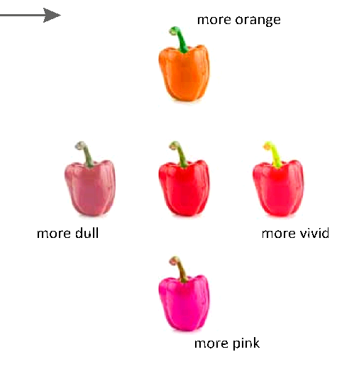
Whilst the CFI says something about the average colour shift compared to the reference light source, the Colour Gamut provides additional information on the direction in which said shift takes place, in terms of hue and saturation.
Concretely the colour space with 99 colours is split into 16 zones (bins), on which the average deviation per zone is expressed graphically. These colours are interconnected and form the colour gamut area. If this area of the test light source is the same as the reference light source, the Rg score is 100. If this area is greater than the reference light source, the Rg score is >100, which means that the test source reflects a richer colour palette than the reference light source. If the area is smaller than the reference source, the Rg score is < 100.
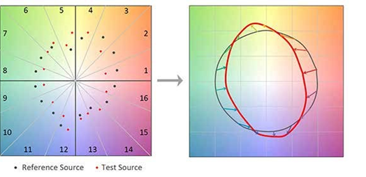
Fig. 25: The average colour values for each bin are indicated for both the test source (red) and for the reference source (black). The gamut area consists of the surface between the connected points (right). This shows to what extent the test source differs from the reference source.
In order to reflect the quality of a light source, account must be taken of both scores: Rf and Rg. A light source with a high Rf, does not necessarily have a high Rg score. And a light source with a low Rf can give specific applications a more suitable colour rendering thanks to a high Rg score. If an Rg greater than 100 must be achieved, the Rf must necessarily be less than Rf 100.
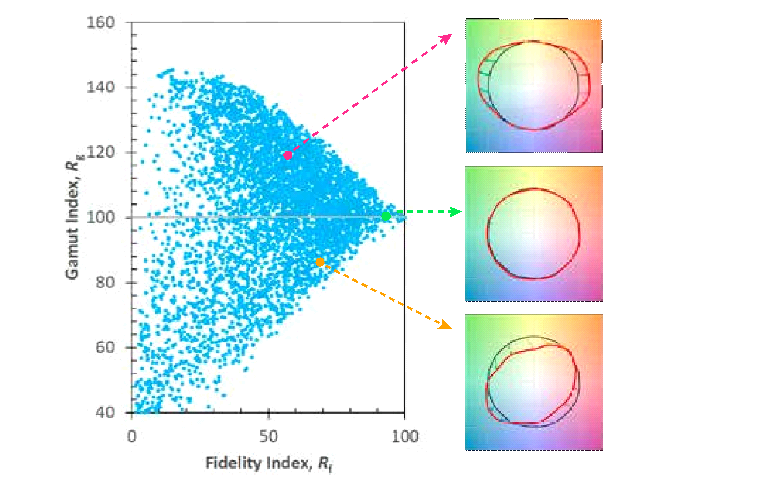
Fig. 26: The graph above shows the range of actual light sources (blue). The first light source (pink) has a
relatively low Rf value, but a high Rg value (i.e., more saturated colours than reference light source). The second
one (green) is located approximately on the axis of 100 Rg and, therefore, is particularly close to the reference light source.
The third one (orange), although it has a high Rf value, has a lower colour gamut than the reference light source.
How will we handle it in the future?
The proposal presented by the IES is being considered by the IEC. The current report only includes a proposal for measuring and quantifying colour rendering. Application standards are to follow at a later stage. For it is also possible to focus on specific hues with the new system. For example, good colour rendering of red hues is important for the illumination of meat, (red) fruit and skin tones, whilst blue hues are critical at a fishmonger’s.
In short
- A high CRI does not guarantee the best colour application or acceptance.
- The old index (CRI or Ra) is not only based on a dated colour palette, it does not provide information on intensity and hue either. Especially with LED technology – which allows for more colour variations than conventional light sources – CRI provides insufficient information.
- The new method (Colour Fidelity Index or CFI) suggested by the IES is not only based on a richer and updated colour palette, but is further complemented by an additional parameter (Colour Gamut, Rg). The graphical representation of Rg makes it possible to visualise in which colours the test light source scores better than the reference light source.
- Thanks to the new method TM-30-15 you can, depending on your application, choose the most appropriate source
Sources:
Houser, K. (2016). LumeNet Workshop for PhD Students.
Royer M., David A. & Whitehead L. (2015). A Technical Discussion of IES TM-30-15.
ETAP Lighting LED Dosier Edition 7
BINNING
During production, LEDs in the same batch or series display various properties, for example with respect to intensity and colour. The use of a mixture of various LEDs in the same luminaire would therefore inevitably lead to various luminous
intensity levels and various light colours, which is why we BIN 1 practise ‘binning’.
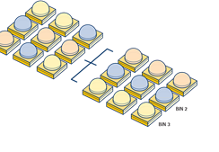
Fig. 27:The principle of binning such as:
- Colour binning: sorting according to colour coordinates (x,y), centred around individual colour temperatures. y 0.9
- Flux binning: sorting according to luminous flux, measuredin lumen (lm). 0.8
- Voltage binning: sorting according to forward voltage, 0.7 measured in Volt. 0.6
By selecting a specific ‘colour bin’, constant light quality is 0.5 guaranteed. LEDs in the same bin therefore have the same 0.4
appearance. Differences in colour bins attract attention when a wall is being uniformly illuminated. In the study of colour
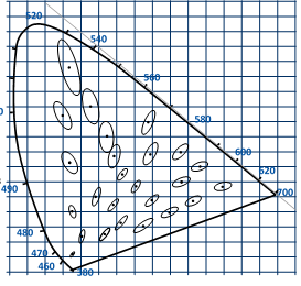
vision, the so-called Mc Adam ellipse (see figure 28) is used, 0.2 which is a region on the CIE diagram, which includes all colours 0.1 indistinguishable to the average human eye from the colour
at the centre of the ellipse. LED manufacturers use SDCM 0.0 0.0 0.1 0.2 0.3 0.4 0.5 0.6 0.7 0.8 x (Standard Deviation Colour Matching), whereby 1 SDCM equals
How does ETAP apply binning to luminaires?
ETAP follows the binning policy of qualified LED manufacturers, who develop said policy in accordance with technical advances, new process management, logistical aspects, etc. The changes do not affect the end user: the amended methods result in a uniform colour temperature. ETAP luminaires (with low-power LEDs, high-power LEDs as well as chip-on-board LEDs) satisfy 3 SDCM.
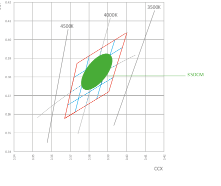
Fig. 29: Illustration of binning principle
RADIATION (IR/UV)
LEDs do not develop ultraviolet (UV) or infrared (IR) radiation in the light beam*, which makes them highly suitable for environments where such radiation is to be avoided as in museums, stores with foodstuffs or clothing shops.
The LED itself does generate heat, but it is led to the back, away from the object to be lit (we will come back to this later – see Section 2.4). Also the radiated light beam represents energy, which is converted into heat as it is absorbed.
* The housing, by contrast, does generate IR radiation (through heat).
LIGHT TREATMENT
LIGHT DISTRIBUTION/TYPES OF OPTICS
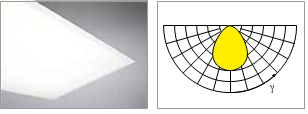
Most LEDs have a wide light distribution and emit light at an angle from 80 to 140° (full angle). Secondary and tertiary optics (reflectors, refractors and diffusers) can be used to achieve specific light distributions. Appropriate light distribution is important to minimise specific power and hence also energy consumption in any given application. a. Reflection
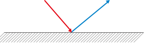
The desired light distribution is created by reflecting the light on a surface.
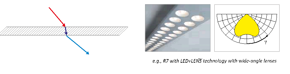
Refraction
The light is sent through a transparent material (e.g., lens) and is bent due to the optical density (refractive index) and the shape of the material surface and subsequently sent in the right direction.
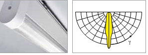
eg. E4 with DUAL•LENS technology with narrow-angle lens
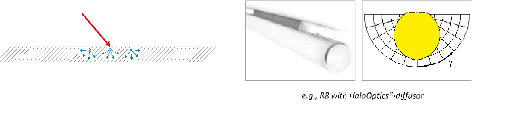
Diffusion or multiple deflections
The light is diffused:
A. on a material surface by means of a surface structure
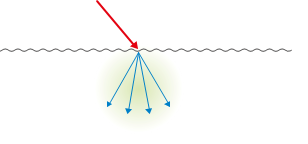
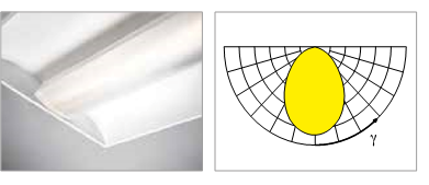
B. in a material volume by means of inclusions.
With the constant improvement in LED performance and maximum power, source luminance also increases rapidly. This luminance can easily reach 10 to 100 million cd/m². The smaller the surface from which the light emanates, the greater the light source’s luminance can become.
A few examples of source luminances:
- Linear fluorescent – T8 14,000 cd/m²
- Linear fluorescent – T5 15,000-20,000 cd/m² to 17,000 cd/m² (HE) and 20,000-33,000 cd/m² (HO)
- Compact fluorescent e.g., 26 W 50,000 cd/m²
- Naked LED 3 W (100 lm) 100,000,000 cd/m²
- Sun 1,000,000.000 cd/m² (=10 x LED)
A well thought-out optical design is therefore an absolute necessity in order to diffuse the light from these bright point sources, avoid direct exposure and decrease glare. To do so, we are able to use lenses, reflectors as well as diffusers. A few examples:
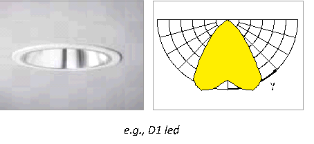
- D4 downlight (UGR<19, luminance <1000 cd/m² at 65°):
◦ Diffusion of light source across large surfaces in order to limit luminance.
◦ Use of lenses with textured surface for the diffusion of peak luminance per light source.
- U2 with LED: the light source is spread over the entire luminaire. The MesoOpticsTM diffuser eliminates disturbing luminances and allows for controlled light distribution.
Since the traditional UGR calculation method does not take into account luminance differences within the same luminaire or optics, research is being conducted at this time to improve the current UGR model. Here so-called luminance images are used, which reflect in detail luminance variations within the light-emitting surface of a luminaire.
ELECTRICAL SAFETY
LEDs work at a low voltage (typically about 3V), therefore it is often thought that electrical safety is not a concern. Currently, lighting solutions with LEDs can run at voltages of 100V or more. As a result, we must take additional measures in order to make the fittings safe to touch.
LEDs in series increase voltage
LEDs in luminaires are preferably connected in series where possible. The logical result, however, is that the voltage increases. One of the benefits of LEDs is that they run on low voltage with a difference in voltage of approximately 3V per LED. But if 30 LEDs are connected in series within one luminaire, you already have 90V. There are even LED drivers that can generate an output voltage in excess of 200V. These require further protection electrically.
Additional insulation needed from 24V
| AC | DC |
| V< 25 VRMS (IRMS < 0,7 mA) | < 60 VDC (IDC < 2 mA) |
| 25 VRMS < V < 60 VRMS | < 60 VDC < V < 120 VDC |
| 60 VRMS < V < 120 VRMS |
Fig. 31: According to the international standards IEC 61347 up to 24V (AC) or 60V (DC) there is no risk in touching (green). In LED luminaires with higher output voltage (red) additional safety measures should be taken.
International standards (IEC 61347) stipulate that above 24V[1], extra measures should be taken to make the luminaires safe. LEDs and other current-conductive parts should not be accessible from the outside. A solution must be found so that the LED can only be touched with special tools after opening. Moreover there must be adequate basic insulation between all touchable conductive and all live parts of the luminaire. In practical terms, ETAP provides sufficient air and maintenance space and uses electrically insulated material without affecting thermal management.
Light source replaceable or not?
The new edition of standard EN 60598 determines whether the light source for LED luminaires is: A. Not replaceable (luminaire is to be destroyed to access the light source).
- Replaceable by the user (light source easily and safely replaceable).
- Replaceable by the manufacturer (light source must be protected by a shield with at least two independent fastenings and cannot be dismantled without tools).
[1] The driver insulation grade determines whether further safety measures are required.
The new edition of standard EN 60598 determines whether the light source for LED luminaires is: A. Not replaceable (luminaire is to be destroyed to access the light source).
- Replaceable by the user (light source easily and safely replaceable).
- Replaceable by the manufacturer (light source must be protected by a shield with at least two independent fastenings and cannot be dismantled without tools).
Luminaires within this last C category must, since 2017, come with a high voltage warning on the luminaires.
PHOTOBIOLOGICAL SAFETY
The European standard for photobiological safety EN 62471 describes a classification system that indicates whether a lamp or luminaire poses a risk of eye and skin damage. Given the high luminance resulting from many high-power LEDs, there is a risk of eye damage. That is why it is important that the photobiological safety be measured correctly and published clearly.
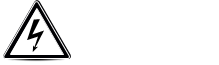
LED light contains almost no light from the ultraviolet or infrared spectrum, and is therefore not harmful to the skin. It does, however, provide a high peak in the blue spectrum which, when looking into a bright light source (for a long period of time), may result in irreversible damage to the retina, the so-called Blue Light Hazard. (BLH)
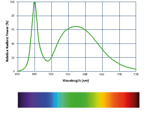
Fig. 32: Because LED light contains a high peak in the blue spectrum, sufficient attention must be paid to protective measures
Four risk groups
Whether the risk is real, depends on several factors: capacity of the LED, colour temperature, but also light distribution and distance to the luminaire play an important role.
To allow users to estimate the risk, the standard EN 62471 determines that lamps and luminaries must be divided into four risk groups. For the Blue Light Hazard, those groups are defined as follows:
- Risk group 0 (‘exempt’ group): this means that there is no danger, even with unlimited viewing of the light source.
- Risk group 1: The risk is limited, no more than 10,000 seconds of viewing is allowed (just under 3 hours).
- Risk group 2: up to 100 seconds of viewing is allowed.
- Risk group 3: up to 0.25 seconds of viewing is allowed. This is shorter than the natural aversion response of the eye.
[1] The driver insulation grade determines whether further safety measures are required.
Since EN 62471 is a theoretical classification defined on the basis of a fixed viewing distance, in addition, a practice guideline has been developed (IEC/TR 62778), which replaces the current standard EN62471 as of 2017. The risk of BLH in fact also depends on the viewing distance (distance between eye and LED). Normally, one does not look into a luminaire from a short distance, although short viewing distances actually do occur, for example in technical maintenance work. IEC/TR 62778 describes within which distances a given luminaire belongs to a specific BLH risk group (so-called limit distances).
Some examples:
- Diffusers belong to risk group 0 (RG 0), regardless of the viewing distance, e.g., Kardó, R8, U2.
- Downlights and LED+LENSTM luminaires belong to RG 1, regardless of the viewing distance.…
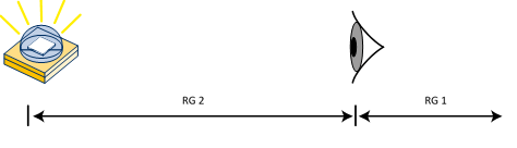
- For the light source in Figure 36, RG 1/RG 0 cm – 2 applies with a limit distance x cm, which means that the light source belongs to RG 2 for viewing distances under x cm.
The extent to which protective measures are required depends on the application. If light sources have a limit distance RG 1/RG 2, this must be specified as such, together with a warning not to look directly into the light source.
Today’s bare white LEDs (used in general lighting) in the worst case belong to group 2, never to group 3. In most luminaires a lens or diffuser behind those LEDs optically magnify the image of the source, thereby reducing peak luminances. This will in most cases result in a lower risk class.
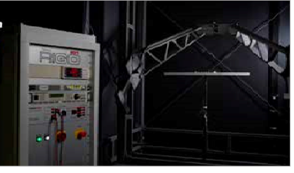
ETAP Lighting’s Spectrometer to conduct measurements
Measure correctly, publish clearly
To which group a luminaire belongs is determined according to a specific measurement procedure, using specialised instruments (spectrometer). ETAP has the proper setup and instruments to carry out measurements in-house. This means that ETAP is able to carefully screen all luminaires for photobiological safety. The solution’s eventual risk group will be published on the website and in the product documentation.
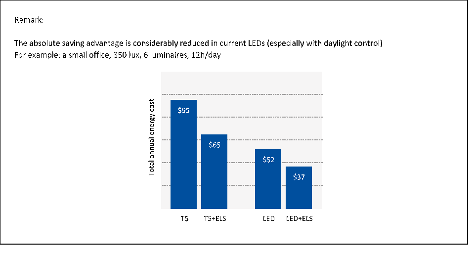
INTEGRATED LIGHT MANAGEMENT
LEDs are not only an energy-efficient light source, they also work perfectly with light control systems. This combination allows for a high savings potential, but also creates a few further advantages: LEDs can be dimmed more efficiently than fluorescent lamps and their service life is not shortened by frequent switching. Finally you can also compensate for the degradation of your LED installation with daylight-dependent light control.
The best known light control systems include motion detection, which dim or switch the light when users enter or leave a space, and daylight control, whereby the light is dimmed depending on the amount of daylight entering a space. A combination of both systems can save 55% or more energy in specific situations. Currently one in six luminaires marketed by ETAP, is fitted with individual daylight control.
LEDs are less sensitive to switching
LEDs have a number of specific features that make them particularly suitable for use with light control systems. Frequent on and off switching and/or dimming has little impact on the LEDs’ service life* in most applications. This in contrast to fluorescent lamps, which when switched on each time lose a small part of the emitter material in the lamp. This can be seen, for example, in the ends darkening in the lamp. In spaces with relatively short presences – just think of sanitary facilities or corridors – we see that the replacement frequency for fluorescent lamps quickly adds up.
LEDs do not have that problem. Since an LED is an electronic component, which is impervious to frequent switching. In addition, LEDs instantly provide full luminous flux when switched on, which increases user comfort when entering the space.
* Except for applications where LEDs are subject to extreme temperatures.
DRIVERS
FLICKER
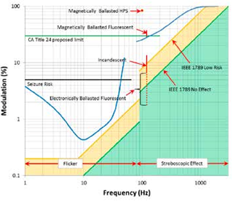
Variations in light output are generally referred to as Temporal Light Artifacts (TLA), ranging from voltage dips to periodic light flicker. Protracted variations cause visible flicker or stroboscopic effects. The difference between both categories is primarily determined by the frequency: whilst visible flicker is caused by slow fluctuations (to approximately 100 Hz) high fluctuations (> 200 Hz) primarily lead to stroboscopic effects. Flicker not only results in visual irritation, but can also lead to headaches, neurological issues (epilepsy) or decreased focus. Stroboscopic effects in turn result in visually faulty images (just think of apparently retarded movements of running machines), which may lead to dangerous conditions.
Not everyone is equally sensitive to light variations. Research[1] suggests that, for example, 30% of all people observe stroboscopic effects at a frequency of 300 Hz. 5% experience major discomfort.
[1] Study by the Lighting Research Center in Detroit, source: Last van led? Allicht, 9th volume, no. 6, June 2016
Flicker and stroboscopic effects are no new phenomena: in traditional light sources (e.g., incandescents or fluorescent lamps) TLAs are a wellknown phenomenon. In fluorescent lamps this problem could be resolved structurally using electronic ballasts. Why is it once again a major issue in LED lighting? LEDs in themselves are a particularly stable light source, the only thing is that they react much more quickly. Whilst traditional lamps react more slowly (incandescents due to warming and cooling of the filament, fluorescent lamps due to the afterglow time of phosphorous), LEDs react immediately after every change in control, and therefore also after any irregularity in said control. Consequently the problem is not in the light source, but in the driver.
High-quality LED solutions are developed in such a way that they prevent flicker, using a quality driver that filters out variations in current. There are nonetheless numerous solutions on the market that pay no or insufficient attention to the issue, as a result of which people – whether or not consciously – experience major discomfort in their work. That is why there was a need for a new standard to measure flicker in LED lighting as well as to establish clear acceptance boundaries.
[1] Study by the Lighting Research Center in Detroit, source: Last van led? Allicht, 9th volume, no. 6, June 2016
The old standard (IEC TR 61547-1), which applied to traditional light sources such as fluorescent and incandescent lamps could no longer be used since LEDs feature more complex signals, made up of several frequencies and a greater frequency range. In addition, in LED lighting, both the control and the light source must be taken into account, whilst the lamp actually used to be left out of the equation in measurements.
There used to be two qualification methods/metrics:
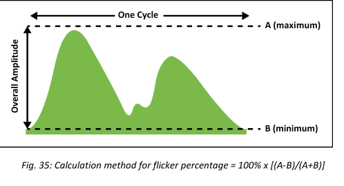
- Flicker percentage: based on the difference between minimum and maximum lamp output, expressed in %. For magnetic ballasts this percentage is typically 15 to 30%. The variation for inferior LED solutions is for that matter in the same range.
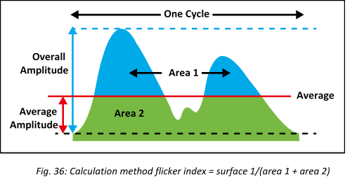
- Another way of quantifying flicker is the flicker index, where the surface above average is compared with the total surface
These old measuring methods, however, do not take into account the frequency, which was not necessary, as traditional light sources for the most part showed the same frequency (e.g., 100 Hz in fluorescent lighting). As long as the peaks in the measuring curves are the same, you will get the same flicker percentage and index for two different frequencies. Since the control of LEDs is made up of different signals with a broad spectral distribution (frequency range) and modulation depth, the aforementioned measuring methods are no longer sufficient.
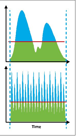
A frequently used dimming technique in drivers, PWM (Pulse Width Modulation), can therefore not be measured in this way either. Here too the frequency determines whether users experience discomfort or not. Only at high frequency and/or low modulation depth, is PWM acceptable.
In which direction the standard has been revised?
In the new metrics, variations in the output of the light source are measured using a sensor, where filtering by the human eye is simulated. It studies how light output changes over time. The result is a curve that shows the luminous flux over time.
Subsequently a signal analysis is carried out on this measuring signal, for two frequency ranges (< 100 Hz, > 100 Hz). The results are two limit values, for flicker (Pst or short-term flicker metrics) and for stroboscopic effects (SVM or Stroboscopic Visibility Measure).
Both limits are shown to illustrate Wilkins’ graphic (blue) for a pure signal (one frequency), but can also be generalised towards a complex (LED) signal (see p. 33, fig. 34: study of Wilkins). Acceptance boundaries established on the basis of these calculations correspond with a 50% risk, i.e., there is a 50% likelihood that people will experience discomfort.
What you have to remember
Stable light output is – next to UGR/glare and colour rendering – an important quality aspect of LED lighting. That is why, from the very beginning, ETAP has been focusing on the use of quality LED drivers to exclude flicker and stroboscopic effects. In the meantime, the IEC (International Electrotechnical Commission) proposed a revision of the IEC/TR 61547-1 standard (Voltage fluctuation immunity test), which allows to qualify drivers in accordance with objective assessment criteria.
Relevant standards on this subject:
- IEC 61000-3-3: Voltage fluctuations limits.
- IEC 61000-4-15 (ed. 2): Flicker meter (PST )
- IEEE 1789-2015: Recommended Practices for Modulating Current in High-Brightness LEDs (SVM )
. QUALITY CRITERIA FOR DRIVERS
The driver is one of the most critical components in LED solutions. The quality of LED luminaires not only depends on the LED light source and optical design, but also on the efficiency and reliability of the driver. A good LED driver must meet seven quality requirements:
Lifetime.
The driver must at least have the same assumed lifespan as the LEDs.
Efficiency.
One of the success factors of LEDs is energy efficiency. Therefore the conversion of mains voltage into current must be as efficient as possible. A good LED driver has an efficiency of at least 85%.
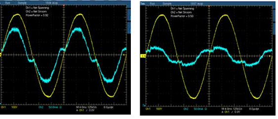
Power factor.
The power factor is a technical indicator of the driver that shows how closely the current of the waveform approximates the sinusoidal reference of the voltage. The power factor (λ) is composed of two parts: the shift between voltage and current (cos ϕ) and the distortion of the current (harmonics or Total Harmonic Distortion). The smaller the shift and distortion of the waveform, the fewer losses and pollution on the energy supplier’s distribution network. In ETAP LED drivers we exclusively work with a power factor in excess of 0.9.
Electromagnetic compatibility (EMC).
The driver should minimise electromagnetic interference in its surrounding area and, simultaneously, be influenced as little as possible by electromagnetic interference from the surrounding area. Therefore proper electromagnetic compatibility is crucial.
Switching current (Inrush current).
When an LED driver is put under power there will be a high peak current on the net for a short period of time (a fraction of a millisecond), because at the start condensers are being charged. In drivers with low switching current, the circuit breakers are not deactivated when a number of luminaires are turned on.
Waveform current.
Good quality output current prevents intensity fluctuations, so that no flicker or stroboscopic effects will occur.
Mains voltage filtering.
Pollution of the electricity grid may cause low-frequency light flicker (+/- 50 Hz), among others. The rapid switching capability of LEDs makes them highly visible, which is perceived as highly disturbing. A good LED driver ensures that the pollution of the electricity grid does not affect the output current, so that the luminous flux remains stable. The standard IEC/TR61 547-1 (An objective voltage fluctuation immunity test method) describes the measuring process to quantify light fluctuations.
Drivers are therefore crucial components in all LED solutions. High-quality drivers can be recognised by requesting the technical fact sheets from the manufacturer to check if the above quality requirements are met. ETAP always provides quality LED drivers, perfectly adapted to the solution and thoroughly tested in our labs.
TYPES OF CONTROL
LEDs are current-controlled components. The current is directly responsible for the luminous output and must therefore be carefully adjusted. Two control methods are used:
-
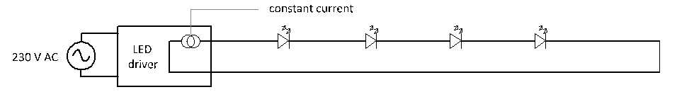
Constant current sources
Directly convert mains voltage into constant current. This method yields the highest efficiency and is the most cost-effective method. The drawback is that modules with a constant current source can only be connected in series, which is more difficult in terms of installation. In addition, the required output voltage adds up quickly (>100 V) for higher levels.
Examples:
- Office luminaires: U3, U7, etc.
- Industrial luminaires: E5, E7, etc.
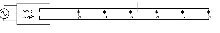
Constant voltage sources
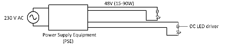
Power supplies that convert mains voltage into carefully controlled voltage. When they are used with LEDs or LED modules, these supplies must always be fitted with a current limiter (e.g., a resistance) or a DC LED driver that converts direct voltage into constant current. The major advantage of voltage sources is that several modules can be easily connected in parallel.
Examples:
- DC bus system: DC LED driver integrated in the cable
constant current DC LED driver
- PoE (Power over Ethernet)
CLO Drivers
First, the limitations of CLO should be well understood:
- CLO works by a time based boost of the driver output current in a preprogrammed linear or piecewise linear fashion. Most drivers are restricted to a maximum current increase of 30% (70% to 100%). The compensation curve has to be programmed in advance by the luminaire manufacturer.
- CLO as a justification to declare L100 implies that all depreciation mechanisms have been taken into account. This includes led depreciation (LLMF), but equally well led mortality (Cy), degradation of any optical active parts and finally environmental effects (LMF/RMF). The latter poses already an issue: RMF/LMF are application dependent (maintenance scheme & time frame) and generally not known to the luminaire manufacturer.
- LLMF can be estimated from LM-80/TM-21, but this method has reached practical limits: with technology advances – extrapolation quality is increasingly being affected by growing uncertainties and noise, and real led behavior can deviate substantially from TM-21. Also, as the LLMF represents median values (B50), the L100 level from a CLO implementation can never been declared as B0!
- CLO does not measure actual output levels. Hence, even with CLO enabled the light output can deviate substantially from the projections meaning CLO is never a guarantee for MF = 100%.
DIMMING
LEDs can be efficiently dimmed over a broad range (from nearly 0% to 100%) or dynamically controlled, which is possible on the basis of standardised dimming methods such as DALI, 1–10 V or TouchDim. Dimmer losses in LEDs in the lower dim ranges are comparable to dimmer losses in fluorescent lights with the latest dim ballasts. When fully dimmed the residual power consumption is practically negligible. LEDs are therefore highly suitable for integration into programmed, dynamic environments.
In practice there are two dimming techniques: by reducing the current level (AM or Amplitude Modulation) or reducing the current into pulses of increasingly shorter duration (PMW or Pulse Width Modulation) or hybrid. Each of these three applications has its pros and cons. Our specialists will be happy to help with concrete advice.
All known dimming systems can in theory also be applied to LED lighting:
DALI
- 1-10 V (applied less frequently in LED lighting )
- TouchDim
- DMX (applied less often to lighting, primarily used in the theatre)
- Phase on/off (primarily residential market)
- Bluetooth (Casambi, BLE, …)
Output and specific luminous flux typically drop under lower power. For example, downlights with power consumption under 20W are usually less efficient than 40W luminaires or higher.
It is important that the efficiency and the power factor remain the same when using a dimmer.
The maximum achievable efficiency for a driver is determined by the nominal power for which the driver was designed (see Figure 40). For drivers with a nominal power <25W maximum efficiency will never be greater than 80-85%. For drivers with a power greater than approx. 35 W maximum efficiencies of 90% and higher can be achieved.
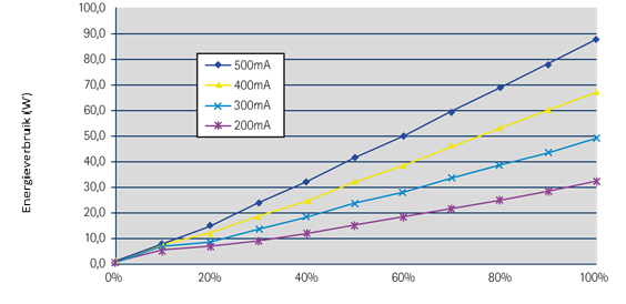
Fig. 39: Effect of dimming on power consumption
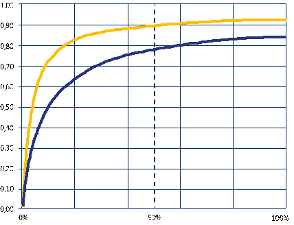
Fig. 40: For drivers with a high power factor (left), the waveform of the current (blue) shows little distortion and shifting compared to the voltage (yellow). This is the case, however for supplies with a low power factor (right).
The above graphic shows that the actual efficiency of a driver also depends on the load. For a quality driver the efficiency will remain fairly constant to a minimum load of 50-60%. For lower loads efficiency decreases significantly. That is why it is important to gear LED module and driver to each other, so that the driver always runs in its optimal operating range.
What to pay attention to as a lighting consumer
OBJECTIVE QUALITY INFORMATION
There did not used to be a directive or normative framework in Europe on the publication of quality data of LED luminaires. Manufacturers did publish information, but it was difficult to compare as a consumer. For example: attractive figures could be published for lifespan, without mentioning how these figures had been reached. Or light output and lifespan were published for the LED light source alone, whilst they are largely determined by the optics and the luminaire design. The lack of uniformity was inconvenient for consumers, who often had to compare apples and oranges.
In the beginning of 2018, Lighting Europe has issued a guidance paper on the subject: “Evaluating performance of LED based luminaires”. This article sums up the lighting industry’s consensus on the parameters you should find on a quality lighting manufacturer’s datasheet.
Six initial performance criteria
Lighting Europe recommends comparing the following parameters.
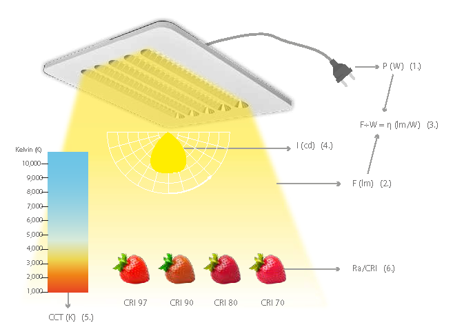
1. Rated input power (P in Watt)
2. Rated luminous flux (flux Φ in Lumen)
3. Rated luminous efficacy (η in Lumen per Watt)
4. Rated luminous intensity distribution (in candela or candela per kilolumen)
5. Rated correlated colour temperature (CCT in Kelvin)
6. Rated colour rendering index (CRI)
Points of special interest
Beware: the published power involves the full power drawn by the luminaire, including the driver or potential external control gear. All too often the power of the LED module is reported and driver losses are not factored in.
Luminous flux and efficiency involve the complete luminaire, and should not be confused with the luminous flux and efficiency of the LED modules. Here too, in practice, optical losses in the secondary optics are not factored in. Furthermore it is important that the luminous flux be provided at the actual operating temperature of the LEDs in the luminaire, and not at a standard 25°C!
For absorbed power, efficiency as well as luminous flux, it is recommended to also explicitly report the matching performance temperature (Tq), even if it is 25°C (standard), as the declared figures all depend on the specific ambient temperature. For deviating temperatures, the values for the provided publication may deviate (just think of recessed fixtures in a ceiling with temperatures reaching 35°C).
Two parameters with respect to lifespan
Quality LED luminaires potentially have a very long service life. During this period, the luminous flux will nonetheless deteriorate to some degree. In order to be able to objectively compare lighting solutions it is recommended to compare the residual luminous flux for the same number of burning hours, instead of comparing duration with assumed light degradation.
The following two factors are important to specify useful life:
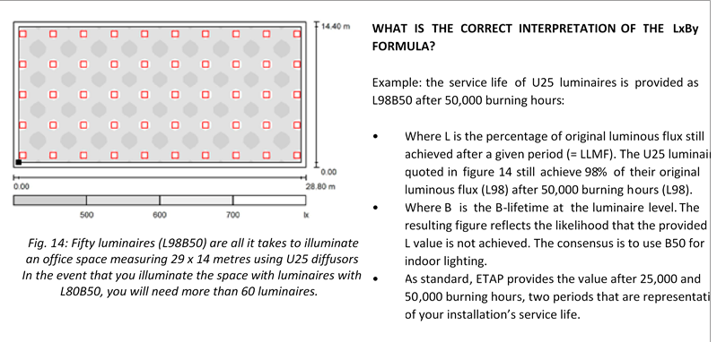
1. Gradual light output degradation. Useful life is described by a luminaire’s LxBy value. Lighting Europe suggests only using “B50” values, which are median values. The latter are considered to be sufficiently precise for practical calculations, and are furthermore the only values that can be backed by standardised measurements. Here B50 must not be explicitly mentioned and only the Lx value published for an assumed number of burning hours. This is the percentage of the initial luminous flux still delivered on average by a luminaire after the reported number of burning hours. ETAP represents this figure as the LLMF value (Lamp Lumen Maintenance Factor) for a given performance temperature.
2. Abrupt failure of the device. The abrupt failure of an LED luminaire can have various reasons: driver failure, LED module failure, poor connections, corrosion, etc. However, few actual data are currently available on the subject and applicable standards are also lacking. Since in practice it has often appeared that for indoor applications, the driver is by far the most critical component, Lighting Europe suggests using the driver’s expected failure percentage today, expressed as Cx whereby x represents the expected failure (in %) during the useful Lx lifespan.
How many burning hours do you really need?
Lighting Europe recommends limiting lifespan estimates to maximum 100,000 burning hours, unless it is explicitly required in highly specific projects and can be backed by more extensive tests. The reliability of lifespan claims quickly becomes inaccurate in any case above 36,000 or 50,000 burning hours, depending on the number of test hours the manufacturers have available. For that matter, it appears from practice that a lifespan of more than 50,000 burning hours is rarely necessary for most indoor applications.
As the required project lifespan and matching number of burning hours may vary considerably between applications, Lighting Europe further suggests specifying the above lifespan (Lx – Cx) factors for different burning hours, e.g., 35,000, 50,000, 75,000 and/or 100,000 hours.
CHOICE CRITERIA
What do you have to pay attention to concretely if you want to have LED lighting installed? Good LED lighting must be efficient, but also factors such as colour rendering and comfort are getting increasingly important. A few questions that can help you to choose the right LED lighting:
A. What is the efficiency of the LED luminaires?
In general the following applies: the greater the specific luminous flux (lm/W), the more efficient the LED. But also look at light distribution, for example, which can have a major impact on specific power (W/m2/100 lux).
B. How is the light distribution?
A suitable light distribution is important in order to keep specific power and hence energy consumption as low as possible in every application. The size of the space, the desired lighting level (horizontal and vertical) determine the choice of a safe specific light distribution.
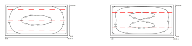
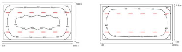
In smaller offices the light is aimed where you want it with the medium-angle lens. In this way you can considerably limit the specific power:
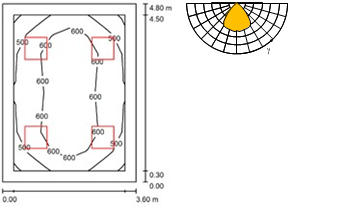
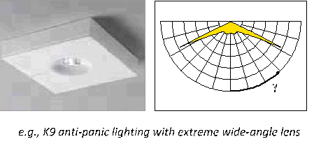
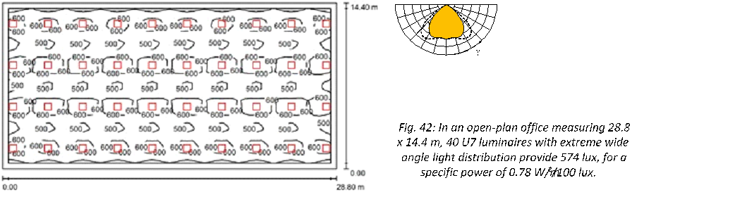
In large office spaces you can minimise intervals and reduce the number of luminaires using the extreme wide-angle lens:
C. How do you want to experience the space?
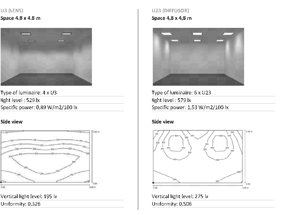
In addition to energy consumption, how you experience the space is also an important factor. All optics illuminate a space differently.
All it takes is 4 lens luminaires (U3) in order to achieve a lumen output of 500 lux. In the event that you illuminate the space with diffuser luminaires (U23), you will need 6 units. In addition to greater vertical lumen output and uniformity, the subjective space perception is different for diffusor luminaires and reflector or lens luminaires. Because the light source is visible and the optics are clearly illuminated, the spaces also appear brighter.
D. What is the lifespan?
In order to have the correct light calculated, it is important to know how long the installation is expected to last. The more accurate the assessment, the less the installation will be over-dimensioned (and the lower the cost). Maybe you do not need 50,000 burning hours at all, but will have enough with 25,000 burning hours? In order to know the correct assessment of the number of burning hours, standard EN15193 publishes an indication of the annual burning hours for specific indoor applications.
E. Do the luminaires have a high LLMF?
The greater the LLMF, the less depreciation. Take a look at the LLMF compared to the anticipated lifespan.
F. How is visual comfort?
Lighting comfort significantly contributes to good working conditions and has a major impact on the well-being and productivity of employees and other users. Therefore also check light levels, glare, stability of the light output and colour properties.
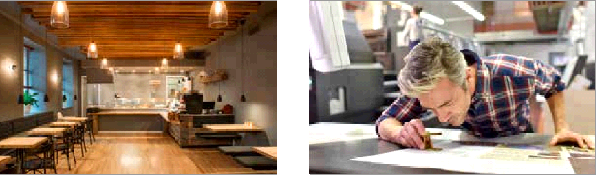
G. Is specific colour rendering or light colour required?
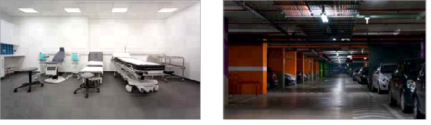
In a business environment, inter alia, good colour rendering and correctly chosen light colour can take precedence over mere efficiency. Also in specific tasks such as quality control, detailed work (e.g., electronics) or in the medical field, good colour properties can be important.
H. In what environment will my luminaires be installed?
An industrial environment has a different pollution factor from an office environment. This is also important information to make a correct light calculation. In addition, the environment can also impose further requirements with respect to electrical robustness, chemical resistance and moisture protection, the luminaires have to comply with. In the event that space pollution is not assessed correctly (RMF or Room Maintenance Factor), this results in an incorrect maintenance factor and therefore an incorrect light calculation:
The study on the left is based on a clean office environment (reflection factors 70/50/20 respectively for ceiling/wall/floor), although it involves an industrial space. As a result too optimistic a maintenance factor is taken into account (0.90): in a 10 x 20 m space you would still achieve 539 lux with 12 E7 luminaires after 50,000 hours. If the correct RMF is taken into account (reflection factors 50/30/10), the calculation is made based on maintenance factor 0.79. From this it appears that in reality you only achieve 432 lux instead of the anticipated 500 lux after 50 ,000 burning hours.
DEVELOPING THE BEST SOLUTION TOGETHER
Our advisors are trained lighting specialists who together with you will seek the right lighting solution, tailored to your project. Based on your wishes and needs, our Research and Development Department will develop a lighting plan that meets all your expectations.
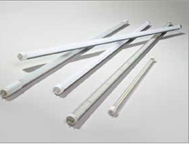
LED TUBES
With luminaires specifically designed for this purpose, LED lamps can also offer numerous benefits. However, if you just replace fluorescent lamps in existing luminaires with LED lamps, quality, comfort and sometimes even safety might suffer.
The EU watches over safe LED tubes
Via the Rapid Alert System, the European Union has blocked sales of various LED tubes (see website of the European Commission http://ec.europa.eu) because they are not in accordance with the 2006/95/EC Low Voltage Directive and the EN 60598 standard for lighting luminaires. In these products there is a risk, among other things, of electric shock during installation as some external components can become electrically charged.
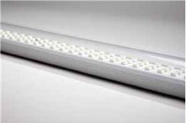
Advantages of LED tubes
LED tubes have numerous practical advantages: they not only have a low energy consumption and a long service life, but are also easy to maintain. If defective the user can replace them (see 6. Electrical safety), without danger of shock. There are also LED tubes in a fully sealed housing, suitable for use in chemical environments. LED tubes in reflector luminaires allow air to be extracted over the reflector, thereby creating a self-cleaning effect.
Internal or external driver?
LED tubes can have an internal or external driver. An external driver allows you to dim the lamps and to easily replace them, if necessary.
Responsible use of LED tubes
It is important to know that you cannot just replace fluorescent lamps with LED tubes. Often the wiring has to be updated, or luminaire components must be exchanged or bypassed. This cancels out the original luminaire manufacturer’s responsibility, but the light quality can also deteriorate as a result: each luminaire is designed for a specific light output and a specific light distribution. By switching to LED tubes without further ado, you will potentially get lower lighting levels, poorer constancy, glare, in short loss of comfort.
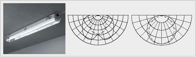
Fig. 45: While an E12/136HFW (with a 1 x 36W-fluorescent lamp) achieves a luminous flux of 3350 lm, and an efficacy of 72 lm/W, the same device with LED-tube achieves, respectively, only 1340 lm and 61 lm/W. Also, the light distribution with a LED tube (right) is different than the one with fluorescent lamp (middle).
But it could be different: if you replace the full internal structure (lamp + reflector) by suitable optics, you can still easily switch to LEDs with existing fluorescent lighting. For example, in the E1 luminaires for high protection factor you can easily replace the lamp and reflector by a renovation module, with LED tube, and continue to use your old luminaires. The result: greater efficiency, significantly less (or no) lamp replacement and unchanged easy comfort.
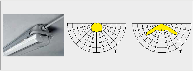
Fig. 46: If the lighting module (lamps and reflector) on a wide-angle E1 with 2 x 58W lamps, is replaced by an LED module with adapted reflector and LED tubes, you will achieve nearly the same luminous flux (6740 instead of 6700 lm), whilst efficiency increases from 90 lm/W to 120 lm/W. The light distribution of the LED version (right) is also more marked than in the fluorescent version (middle ).
LEDs – What will the future bring?
A new dimension in lighting
LEDs have resolutely conquered their place on the lighting market over the past few years and are well on their way to completely replace traditional light sources such as fluorescents and halogens. But in the meantime technological development does not stand still. Whilst up to now designers had been primarily focusing on improved performance and service life, they are slowly discovering the many possibilities offered by LEDs.
More than just a replacement for fluorescents
The fact that LEDs have permanently replaced traditional light sources such as fluorescents or halogens is only logical, given their higher efficiency and longer service life. In addition, the initial drawbacks of LED lighting have undergone a great deal of doctoring. A new generation of more stable drivers resolved the issue of the flicker effect and better adapted optics prevent glare caused by the bright light. The colour quality has also improved enormously as LEDs typically have a better distributed broadband spectrum than the narrowband spectrum of fluorescent lighting. Currently LEDs are available with colour rendering of Ra > 90 to Ra 100. Thanks to the better colour rendering, the same visual comfort can often be achieved at lower lumen outputs.
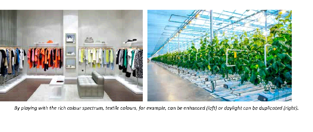
Playing with light and colour
Today designers are discovering, however, that LEDs can be a lot more than an efficient variation of traditional light sources. As an electronic light source, LEDs offer endless possibilities to better gear lighting to specific applications. For example, designers play with colour properties to develop lighting that better showcases textiles or foodstuffs. Thanks to a rich spectrum, LEDs are increasingly approaching the effect of actual sunlight, which promotes plant growth in horticulture. For night-time lighting in hospitals and outdoor applications, for example, redder hues (without blue) are better as they are more favourable for the biorhythm of man and animal.
For every backdrop
A lot of people initially still experienced LED lighting as ‘hard’ or ‘cool’. But thanks to new developments LEDs are increasingly suitable for backdrops that require attractive and cosy lighting. For example, the dim-to-warm effect was developed for hospitality and residential applications. By dimming, not only is the strength of the light reduced, but also the colour temperature. As a result, the light colour leans more to orangey red, as used to be the case when incandescent and halogen lamps were dimmed.
The dim-to-warm effect provides warm, attractive LED lighting
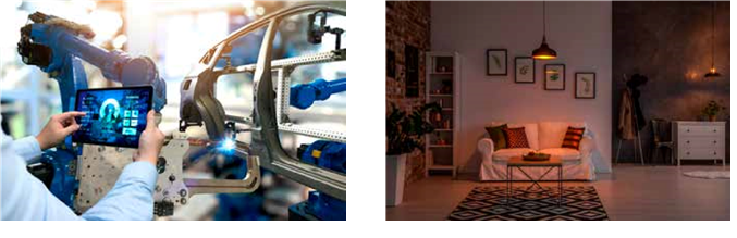
By playing with colour and intensity, we can gear the light to any scenario and environment or even have it evolve depending on the time of day. Dynamic and rich light in the morning, attractive and restful in the evening. This paves the way to fully personalised lighting. Because not everyone experiences light in the same way. Age and gender play a role, just as does light sensitivity. Car manufacturers already experiment in production environments with lighting that is adjusted to the preferences of the employee who is at work at that time.
The automotive industry is experimenting with personalised light tailored to the employee.
Lighting is getting compact and smart
In the meantime LED technology itself has not come to a stop either. LEDs based on laser light for example, already make it possible to create coherent light be
Things (Illustration: freepik.com)
ams spanning great distances, an interesting application for a car’s headlights. We also see a trend towards miniaturisation, whereby miniscule LEDs are placed very close together, each with its own optics, which can be controlled separately. Nanotube LEDs are LEDs in the shape of tubes that can give off as well as detect light.
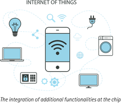
Lastly, experiments are being conducted by adding further functionalities through system integration at the chip level. Drivers, sensors or flow control are integrated into the LED light source, which allows luminaires to be more compact. This development at the same time paves the way to smart lighting and Internet of Things applications, whereby the light points, which our presence almost in every room – communicate with other applications.
The new options made possible with LEDs, go way beyond a mere increase in efficiency. They give lighting a new dimension, which will completely change the market in the coming years. As a result it is becoming increasingly important for lighting manufacturers to listen to customers, and to help them to make the right choice among the extensive range and to develop a solution together, tailored to their needs.
International standards
At www.lightingeurope.org you will find the latest guidelines on LED standards: ‘LightingEurope Guide for the application of the Commission Regulation (EU) No. 1194/2012 setting ecodesign requirements for directional lamps, light emitting diode lamps and related equipment’.
In compliance with the guidelines of the Lighting Industry Liaison Group, these are the international standards with respect to LED lighting:
Australian & New Zealand requirements
Australia falls under similar under similar requirements as Europe. ASNZ require SAA approvals on Drivers installed within luminaires. All luminaire component must be tested and compliant. Energy Safe Victoria “ESV” have guidelines on their website. The Australian and New Zealand standards have set requirements for differing applications as does the Building Codes Australia “BCA”. The biggest challenge for lighting designers with LED lighting is Glare, measured in UGR and uniformity. analysing manufacturers data to determine the quality and performance of a lighting product can be extremely confusing and often the data given is not entirely correct. Often supplier will give “L80:B50” as a measure of the luminaire performance. This is only the performance of the LED diode within the luinaire. The luminaire, if not designed to support the LED diode, can greatly degrade the life of a diode.
Only Emergency and Exit Lighting with ASNZ2293 testing can be installed in Australian and New Zealand.
For more technical papers, please contact Bluelab Design or discuss your technical questions with Bluelab staff
This information was sourced from ETAP Lighting – LED dosier edition 7 2018